
19 min read ·
What It Means to Support a Building on Screw-In Steel Piles
In foundation work, it means a structure supported by screw-in steel piles. Cobbles, boulders or very dense gravel can damage a helix or stop installation.
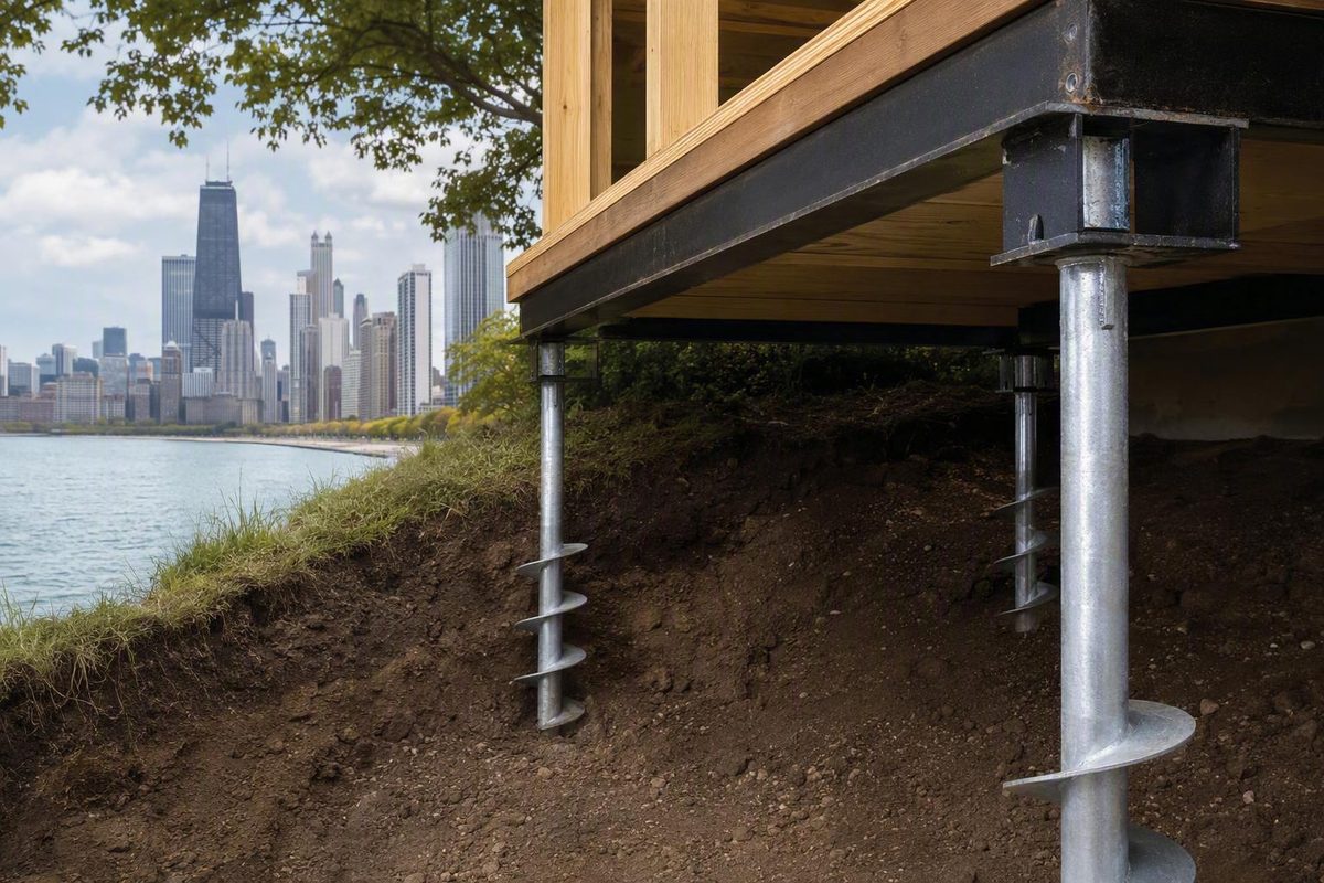
What it means to support a building on screw-in steel piles
First, what does “helical building” mean?
It could describe a visibly twisting tower, but in foundation work, helical usually refers to the piles, piers, or anchors beneath a structure.
A building supported this way can look entirely conventional above ground. Below it, steel foundation elements are rotated into the soil to transfer structural loads to suitable bearing material. Related names include helical pile, screw pile, helical pier, helical anchor, torque anchor, and steel screw-in piling.
The basic concept is consistent: one or more helix-shaped bearing plates are welded to a central steel shaft, and hydraulic rotary equipment advances the assembly into the ground. The plates then help transfer structural loads from the shaft into the surrounding soil, as described in this overview of helical-pile foundations.
A spiral-shaped building is a separate subject. Its visible form raises architectural and engineering questions about geometry, framing, façade construction, wind response, floor layouts, and circulation. Those features do not define a helical-pile foundation. A twisting tower might use another foundation system, while a rectangular house, warehouse, addition, or multistory building might rest on helical piles without displaying any spiral geometry.
This article therefore uses “helical building” to mean a building supported in whole or in part by helical piles. It is an introductory, non-calculational overview—not project-ready guidance. Actual pile selection, capacity, testing, corrosion protection, connections, and approval depend on the site, structure, product system, and applicable requirements.
The parts beneath the building
A typical helical-pile assembly includes several components:
- Lead section: The first shaft segment advanced into the ground.
- Central shaft: The steel member that transmits force between the building connection and the helices. Available configurations include round hollow and square solid shafts.
- Helical bearing plates: One or more steel plates formed into a helix and welded to the shaft.
- Extension sections: Modular shaft segments added as installation proceeds.
- Couplers: Connections, often bolted, that join the lead section and extensions.
- Bracket, cap, or termination assembly: The component that connects the pile to the supported foundation or framing.
The lead section enters the ground first. As its upper end approaches the working level, the installer stops the rotary drive, adds an extension, reconnects the equipment, and continues. This modular arrangement allows installation to proceed toward deeper bearing material without assuming a standard depth.
The shaft configuration is not a superficial product choice. Round hollow and square solid shafts differ in geometry, and manufacturers offer them in different dimensions and material configurations. Likewise, the diameter, thickness, number, and spacing of the helices can vary. Values published for one system should not be transferred to another product or project without the relevant engineering basis.
At the pile head, a bracket or cap transfers force between the pile and the building. Connections can be configured for steel, concrete, or timber construction.
Some systems also place grout around part of the shaft. A displacement component can create an annular space that is filled as installation continues. Grouted and ungrouted systems should not be treated as interchangeable because grout changes the pile configuration and may affect how it responds to loading and surrounding soil. A contractor’s helical-pile component overview illustrates modular extensions, bolted couplers, round and square shafts, and a grouted variation.
A useful project illustration should label:
- Structural bracket or cap
- Ground line
- Extension shaft
- Coupler
- Lead shaft
- One or more helices
- Weak or unsuitable upper soil
- Deeper bearing soil
- Compression and uplift directions
Such a drawing can be more informative than a generic installation photograph because it shows both the manufactured assembly and the soil profile on which performance depends.
How a helical foundation carries building loads
The load path begins in the building. Floors, walls, columns, and framing deliver force to a footing, grade beam, pile cap, or bracket. That connection transfers the force into the steel shaft, which carries it to the helices and surrounding soil.
Under compression, the building pushes downward. The helical plates act as bearing elements that transfer force into the soil. The design must also account for acceptable settlement and structural movement.
Under uplift, force attempts to pull the foundation upward. The pile, couplers, bracket, surrounding soil, and structural connection all form part of the load path.
Lateral forces act sideways. They may arise from wind, seismic effects, earth pressure, equipment, eccentric loading, or slope conditions.
Possible responses include a different shaft configuration, reinforced-concrete grade beams, concrete piers, pile caps, structural bracing, or angled piles. On a slope, a pile installed at an angle is commonly called a battered pile. A supplier’s discussion of helical piers on sloped terrain identifies compression, tension, lateral force, structural bracing, and battered piles as project considerations, although actual suitability remains site-specific.
Commercial sources differ in how they describe lateral behavior. Some broadly state that a helical system can carry horizontal loads, while others emphasize that conventional configurations may need larger shafts or supplemental structural measures when lateral loading governs. These positions are not necessarily irreconcilable: shaft geometry, stiffness, embedment, soil profile, head restraint, grout, and pile arrangement can change the response. The defensible conclusion is that lateral performance must be evaluated for the proposed configuration.
Sources also differ in the importance they assign to shaft-soil interaction. Some descriptions focus primarily on bearing at the helical plates, while others attribute some resistance to shaft interaction, particularly for larger or grouted systems. Helix bearing is a defining feature, but the contribution assigned to the shaft should not be generalized across systems.
Buildings commonly use multiple piles placed beneath columns, walls, grade beams, equipment supports, or other concentrated loads. Pile quantity, layout, spacing, and connections follow the building’s load paths and the site conditions. The connecting structure also affects how forces are distributed among piles.
For that reason, statements such as “one pile supports a house” or “this shaft size supports a commercial building” are not useful design rules. A building category does not determine capacity. Loads, soil, pile geometry, connections, layout, installation, and verification all matter.
From soil investigation to completed connection
A helical foundation should be approached as an engineering and construction sequence rather than simply an installation appointment.
1. Define the structural demands
The project team first identifies the loads reaching the foundation, including relevant compression, uplift, and lateral demands. It also establishes acceptable movement criteria and coordinates preliminary pile locations with columns, walls, grade beams, utilities, and construction sequencing.
This stage determines what the foundation must accomplish. It does not yet establish the final pile type, quantity, or depth.
2. Investigate soil and groundwater
The geotechnical investigation should characterize the soil layers through which the piles are expected to pass and the material intended to provide support. Relevant conditions may include groundwater, fill, weak upper soils, dense gravel, cobbles, boulders, debris, or rock. Soil and groundwater exposure may also influence corrosion planning.
The installation plan therefore needs a response for conditions that differ from the available site information.
3. Review access and exposure
The team evaluates equipment access, overhead clearance, working room, nearby structures, utilities, slope geometry, groundwater, spoil-handling constraints, and any project limits on noise or vibration.
Compact equipment, including mini excavators, may be suitable for some restricted sites. Larger shafts, higher installation demands, or difficult ground may require larger machinery and more operating room. “Restricted access” is therefore a reason to study the system, not proof that the required equipment will fit.
4. Select a preliminary system
The engineers establish a preliminary shaft type, helix configuration, pile count, layout, connection concept, and corrosion approach. They also identify the intended installation and acceptance criteria.
At this stage, grouted and ungrouted systems, bracket types, pile caps, grade beams, and lateral-load measures must be distinguished. Product dimensions or load tables are meaningful only within their stated assumptions and system limitations.
5. Install the piles
A hydraulic rotary drive head applies torque to the pile. The lead section turns into the soil, and installers add extensions as needed. Unlike a driven pile, the element advances primarily through rotation rather than impact.
There is no universal installation depth. Installation proceeds according to the project’s defined criteria and actual ground conditions.
6. Record and inspect the work
Installation records should describe what occurred at each pile rather than simply state that installation is complete. Depending on the project, useful records can include:
- Pile location
- Shaft and helix configuration
- Achieved depth
- Number of extensions
- Recorded installation torque
- Interruptions or deviations
- Refusal or obstruction observations
- Final cutoff and connection information
Inspection may also address couplers, alignment, brackets, welds, reinforcing, grout, caps, or grade beams where those features form part of the work. The exact inspection framework must be established for the project rather than inferred from this general overview.
7. Verify performance when required
Several terms used in pile discussions should remain distinct:
These concepts are related, but they are not synonyms. Torque records may contribute to capacity assessment when an appropriate relationship applies, yet torque alone is not universal proof of final allowable capacity in every soil, product system, or jurisdiction.
The manufacturer’s CHANCE technical design manual treats soil investigation, bearing capacity, safety factors, lateral capacity, buckling, deflection, torque-capacity relationships, equipment calibration, termination criteria, and load testing as separate topics. Its historical references and product information do not, by themselves, establish current approval for an unrelated project.
8. Complete the connection
After pile acceptance, the team completes the bracket, cap, grade beam, footing, or framing connection. Reinforcing, grout, concrete placement, curing, inspection, or testing may still affect when the structure can be loaded.
An ungrouted steel shaft has no pile-shaft concrete curing period, but that does not mean every connected foundation is ready for full loading as soon as rotation stops. The rest of the foundation assembly and the project’s acceptance requirements still govern.
Owners should ask what closeout information will be provided. Depending on the project, that package may include:
- Final pile locations
- Material information
- Shaft and helix configurations
- Installation depths
- Torque records
- Deviations and corrective actions
- Inspection documentation
- Connection details
- Grout information, if applicable
- Test procedures and results, if required
Qualified project professionals and the relevant authority must determine applicable permits, approvals, design criteria, safety factors, inspections, and testing. This article does not provide a jurisdiction-specific compliance pathway.
Where helical piles may fit—and where they may not
Helical piles are often considered when weak near-surface soil makes a shallow foundation impractical or when excavation, access, vibration, or groundwater complicates construction. They may also be evaluated for additions, new buildings, underpinning, interior rehabilitation, and work on slopes.
Rotary installation generally avoids pile-driving impact and may produce less excavated material than foundations formed in large drilled or open excavations. That can be useful where spoil removal through a finished property is difficult or where neighboring structures are sensitive to impact vibration. Compact rotary equipment can also reach some locations that cannot accommodate a conventional pile-driving rig.
Predrilling, obstruction removal, grout, pile caps, or grade beams may also generate material that must be handled.
Slope projects require broader review. Individual piles may encounter compression, uplift, and lateral forces, while the site as a whole may be vulnerable to soil movement. Bracing or battered piles may be considered, but foundation elements do not replace an assessment of overall slope conditions.
Ground obstructions are a central limitation. Cobbles, boulders, very dense gravel, rock, debris, or undocumented fill may deflect a shaft, damage a helix, or stop installation before the intended bearing material is reached. Commercial guidance on helical-pier suitability specifically identifies cobbles, boulders, and very dense gravel as possible causes of deflection or helix damage.
The pile may have encountered an isolated obstruction. A project-specific response might involve review, relocation, permitted predrilling, different equipment, a revised pile configuration, obstruction removal, a changed layout, or another foundation method. The appropriate response cannot be selected from a generic checklist.
Other matters that may govern feasibility include settlement, embedment, buckling through weak soil, pile spacing, load distribution, lateral deformation, connection design, and constructability. Meeting one axial installation criterion does not resolve every possible limit state.
Corrosion also requires a site-specific approach. No generic coating claim establishes a universal service life. A contractor-authored comparison of helical and traditional piles identifies dense or rocky ground, lateral demands, and corrosive exposure as limitations requiring project review.
| Reason to evaluate | Condition requiring added analysis | Possible obstacle |
|---|---|---|
| Weak near-surface soil | Settlement and location of suitable bearing material | Weak deposits extending beyond practical installation |
| High water table | Groundwater effects on construction and durability | Site or environmental constraints |
| Restricted access | Equipment size, headroom, working platform, and installation demands | Equipment cannot reach or operate safely |
| Vibration-sensitive surroundings | Neighboring structures and project limits | Required work is incompatible with site restrictions |
| Limited spoil-handling options | Predrilling, grout, caps, or obstruction removal | Difficult material still requires handling |
| Sloped site | Axial loads, lateral loads, bracing, and overall slope conditions | Active or unstable soil movement |
| Retrofit or historic structure | Existing-foundation condition and connection design | Insufficient clearance or sound connection material |
| New construction | Layout, spacing, caps, grade beams, and sequencing | Utilities or other foundation conflicts |
| Corrosive exposure | Design life and protection approach | Protection cannot satisfy project requirements |
| Variable or obstructed soil | Refusal response and installation tolerances | Cobbles, boulders, dense gravel, debris, or rock |
Helical piles versus other foundation approaches
Foundation selection begins with structural loads, soil, groundwater, access, neighboring structures, vibration limits, durability expectations, approvals, and construction logistics. It should not begin with the assumption that one product is universally preferable.
At a basic level, the methods differ in how they enter or engage the ground:
- Helical piles are rotated into the soil.
- Driven piles advance through impact or vibratory action.
- Drilled shafts or caissons involve drilling or excavation followed by construction of the foundation element.
- Conventional shallow concrete footings require excavation and concrete placement.
- Push or resistance piers are hydraulically pushed into the ground, commonly for underpinning.
Helical piles may be worth evaluating when compact installation equipment, limited excavation, or avoidance of pile-driving impact is important. An ungrouted steel pile shaft also does not require concrete curing. Those points do not prove that the entire foundation will be faster. Inspection, testing, brackets, reinforcing, pile caps, grade beams, concrete work, and obstruction responses may govern the schedule.
The method has its own constraints. Obstructed soil can cause deflection, damage, or refusal. Slender shafts through weak material may require additional review. Lateral loading may call for modified pile geometry or supplemental structural measures. Buried and exposed steel may need a project-specific corrosion strategy.
Push piers should not be conflated with helical piles merely because both can be steel underpinning elements. The CHANCE manual describes resistance piers as elements pushed into the ground using an existing structure as the installation reaction. Helical piles, by contrast, are advanced by rotary torque and do not require an existing building to supply that reaction.
| Evaluation point | Helical piles | Driven piles | Drilled shafts or caissons | Conventional concrete footings |
|---|---|---|---|---|
| Installation action | Rotated into soil | Advanced by impact or vibration | Hole drilled or excavated, then foundation element constructed | Soil excavated and footing built near the surface |
| Excavation and spoils | Often limited, though not necessarily absent | Usually limited along the pile shaft | Drilling or excavation produces material to manage | Requires footing excavation |
| Vibration | Avoids pile-driving impact | Impact or vibration is part of installation | Avoids pile-driving impact, though drilling still affects the site | Excavation and construction equipment create disturbance |
| Access | Compact equipment may be possible | Rig and pile-handling access required | Drill rig, concrete, casing, and spoil access may be required | Excavation, reinforcing, and concrete access required |
| Curing | No shaft curing for an ungrouted steel pile | Depends on pile and connection type | Cast-in-place concrete requires curing | Concrete requires curing |
| Soil obstructions | May cause deflection, damage, or refusal | May impede installation or damage piles | May require different drilling tools or procedures | May complicate excavation |
| Lateral design | Requires configuration-specific review | Requires pile- and group-specific review | Depends on shaft stiffness and soil response | Depends on footing geometry and soil support |
| Capacity verification | Installation records, assessment, inspection, and testing as specified | Driving records and testing as specified | Construction inspection and testing as specified | Soil verification and material inspection as specified |
| Common project contexts | Restricted access, retrofit work, weak surface soil, or vibration-sensitive sites | Projects suited to pile-driving operations | Loads and ground conditions suited to drilled construction | Suitable shallow soil and practical excavation |
This comparison is deliberately qualitative. The supplied evidence does not support ranking these methods by cost, strength, speed, durability, or environmental performance. A meaningful comparison requires alternatives based on the same loads, site information, acceptance criteria, schedule, and allocation of construction risk.
A historic-building example—and what it does not prove
A Winnipeg rehabilitation illustrates how rotary piles can be used in a constrained interior project. It should be read as a contractor-reported case study, not independent proof of general performance.
According to installer VersaPile, the building was constructed in 1930–1931 as the Uptown Theater and later operated as Academy Uptown Lanes. The project retained the historic exterior while replacing the interior with a new retail-and-condominium structure. The installer reports that driven piles raised vibration concerns, while open caissons would have complicated excavation and spoil removal inside the retained shell. It also reports dense glacial till and a primary interior access opening measuring 9 by 10 feet in its Winnipeg case study.
VersaPile reports a preliminary main-structure design load of 150 kips per pile. It says the project used 117 piles for the condominium structure and 24 piles for a vestibule, totaling 141. The reported main-structure configuration was a 4.5-inch-diameter pile with one 16-inch helix; the vestibule used a 3.5-inch-diameter pile with one 12-inch helix. These are reported project-specific configurations, not general selection rules.
The installer further reports that the piles were advanced to refusal in dense glacial till while an on-site engineer recorded installation data. It says all 141 piles were completed in 24 days without notable delays. These figures come from the installer’s account and are not independently verified in the supplied evidence.
The narrow lesson is useful: rotary pile installation can be adapted to an interior rehabilitation where access, vibration, excavation, and spoil movement are significant constraints. The example also shows why separate parts of one development may receive different pile configurations and design loads.
The case study does not disclose complete engineering drawings, full torque records, load-test results, safety factors, comparative bids, final foundation costs, independent completion records, or long-term monitoring. It therefore does not establish that the system was cheaper, safer, faster, or more durable than every alternative. Nor does it prove that no other foundation method could have supported the project.
A preconstruction checklist for owners and project teams
Before selecting a helical foundation, ask questions tied to the actual property rather than relying on generic product claims.
Ground conditions
- Is the available geotechnical information proportionate to the project?
- Which soil layer is expected to provide support?
- What is known about groundwater?
- Are fill, loose soil, dense gravel, cobbles, boulders, debris, or rock likely?
- Has potentially corrosive soil or groundwater exposure been considered?
- What uncertainty remains between investigation points?
Loads and performance
- Have compression, uplift, and lateral demands been identified?
- What settlement and movement limits apply?
- Have pile spacing, load distribution, and possible buckling been addressed?
- How will the pile heads connect to the building?
- Are grade beams, caps, bracing, or battered piles being considered?
- Does a sloped site require a broader stability assessment?
Proposed pile configuration
- How were the shaft type and dimensions selected?
- Why were the helix diameter, number, and spacing chosen?
- How was the preliminary pile quantity established?
- What depth range is anticipated, and how uncertain is it?
- What installation and termination criteria are proposed?
- Is the system grouted or ungrouted?
Capacity verification
- What torque-capacity relationship, if any, is proposed?
- Is that relationship applicable to the specified pile system and site conditions?
- How will torque equipment be calibrated and readings recorded?
- How are estimated ultimate capacity and allowable design load distinguished?
- What field testing, if any, is specified?
- Who reviews and accepts the installation information?
Unexpected conditions
- What happens if high resistance is encountered too shallow?
- How is premature refusal defined for the project?
- What is the response to suspected deflection or damage?
- How will undocumented fill or buried debris be handled?
- Can a pile be relocated without creating structural or spacing conflicts?
- Who may authorize field changes?
- How will deviations and corrective work be documented?
Corrosion and design life
- What site information supports the corrosion assessment?
- What intended design life is being considered?
- Does the approach involve galvanizing, coatings, wraps, grout, sacrificial steel, or another measure?
- How will couplers, brackets, cutoffs, and exposed connections be addressed?
- Are any accessible components expected to require inspection or maintenance?
Construction logistics
- Can the proposed equipment reach every pile location?
- Are doorway width, headroom, operating clearance, and working-platform conditions adequate?
- Have underground and overhead utilities been considered?
- What project restrictions apply to noise or vibration?
- Could predrilling, obstruction removal, grout, caps, or grade beams create spoils?
- How will installation, inspection, testing, connection work, and other trades be sequenced?
- What temporary work may be needed around an existing structure?
Approvals and records
- Who will identify the current local requirements?
- What product documentation is required for the proposed system?
- What permits, reviews, or inspections apply?
- Who is responsible for geotechnical design, structural design, installation review, and field changes?
- What closeout records will the owner receive?
The budget should cover more than an advertised per-pile price. Potential items include site investigation, engineering, mobilization, pile quantity, achieved depth, extensions, equipment access, corrosion protection, brackets, grout, caps, grade beams, testing, inspection, obstruction handling, rejected work, redesign, and remediation.
Frequently asked questions
Is a helical building the same as a spiral-shaped building?
No. The phrase is ambiguous, but in foundation discussions it generally means a building supported by helical piles or piers. The above-ground structure can be rectangular and visually conventional. A spiral-shaped building is a separate architectural and structural subject involving visible geometry, framing, façade design, wind response, and circulation.
Can helical piles support a large or heavily loaded building?
Potentially, but building size alone cannot answer the question. A heavily loaded structure may require different or larger piles, more piles, group arrangements, stronger connections, field testing, or supplemental lateral systems. Feasibility depends on loads, soil, groundwater, access, obstructions, movement limits, corrosion exposure, and applicable approvals. General vendor capacity ranges are not substitutes for project-specific design.
How deep do helical piles have to go?
There is no standard depth. Extensions allow installation to continue toward suitable bearing material, but final depth depends on the defined termination criteria and actual ground conditions. High resistance at shallow depth can indicate an obstruction rather than acceptable support, so depth should not be interpreted in isolation.
Does installation torque prove that a helical pile has enough capacity?
Not automatically. Installation torque can contribute to an estimate when an appropriate system-specific relationship and reliable records are used. Acceptance may also depend on embedment, soil conditions, design criteria, inspection, and testing. Installation torque, estimated ultimate capacity, proof load, tested capacity, and allowable design load are distinct concepts.
Can helical piles be installed under or inside an existing building?
Some retrofit and rehabilitation projects use helical piles inside or beside existing buildings. Modular shafts and compact hydraulic equipment can help where access is restricted. Feasibility still depends on doorway dimensions, headroom, operating clearance, working-platform capacity, required equipment, utility conflicts, existing-foundation condition, and connection design. The Winnipeg project illustrates the possibility, but it does not show that every interior site can accommodate the method.
In most construction coverage, a “helical building” is an ordinary-looking structure supported by screw-in steel piles—not necessarily a visibly twisting landmark. Helical piles may help address particular access, vibration, excavation, soil, slope, or rehabilitation constraints, but their value cannot be separated from the site. The practical goal is to ask better questions about ground conditions, loads, obstructions, lateral behavior, corrosion, installation records, testing, connections, costs, and current approvals—not to select or size a foundation without qualified geotechnical and structural professionals.