
19 min read ·
How Medieval Carpenters Opened the Roof Without a Full Tie Beam
A hammer beam is one of a pair of short timbers projecting inward near the principal rafters. "False hammer-beam roof" has two documented definitions.
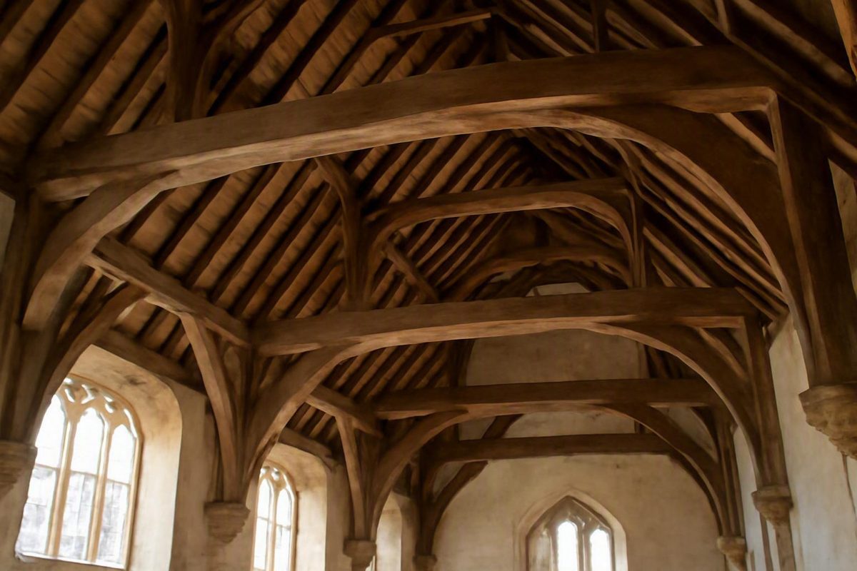
A hammer beam is a short projecting timber used as one part of an open roof frame where a conventional tie beam might otherwise cross the full width of a building. Installed in opposed pairs and combined with braces, posts, rafters, and adequately restrained supports, hammer beams leave the center of the roof open. The result is the lofty interior associated with some of the best-known halls and churches of English Gothic architecture.
That openness can be misleading. Removing the central part of a full-width tie does not remove the forces that the tie would have helped restrain. It redirects them through a more intricate arrangement of timber members, joints, walls or posts, and foundations. Understanding a hammer-beam roof therefore begins with separating its dramatic appearance from its structural action.
What a hammer beam is—and what it is not
Strictly speaking, a hammer beam is one of a pair of short, approximately horizontal timbers projecting inward near the feet of the principal rafters. A full-width tie beam is absent at that level: the two hammer beams occupy only the side portions of the line that a conventional tie would cross, leaving the center open. An illustrated architectural definition similarly describes a hammer beam as a short member attached near the foot of a principal rafter in place of a full tie beam.
Three related meanings often become blurred:
- The individual hammer beam is the short horizontal member projecting from one side of the roof.
- The hammer-beam assembly, often called a hammer-beam truss, is the larger transverse frame of opposed hammer beams, braces, posts, rafters, and associated members.
- The hammer-beam roof is the complete roof formed by repeating those transverse assemblies along the building and connecting them with longitudinal framing.
Two other terms are essential. A rafter is a sloping member that helps support the roof covering. A tie beam is a horizontal member connecting opposing rafters near their feet. In a conventional tied roof, that beam helps prevent the rafter feet and their supports from spreading outward.
The hammer-beam form is primarily associated with open timber roofs, particularly those of late-medieval England. Because the principal framing remains visible from the room below, the roof acts as both a structural system and a major architectural composition. Braces, posts, carved ends, tracery, pendants, paint, and gilding can shape the interior as strongly as columns or vaults.
Spelling varies. Hammer beam is clear when referring to the individual member. Hammer-beam roof and hammer-beam truss use the term as a compound modifier, while hammerbeam roof also appears frequently. These forms generally describe the same architectural family rather than different structural systems.
Not every exposed bracket or short timber beneath a roof is a hammer beam. A bracket may support another beam, stiffen a post-and-beam joint, conceal a connector, or serve only as decoration. A hammer-beam-like silhouette is therefore not proof of structural function.
To identify a likely hammer beam, look for its position within a complete transverse assembly. It should project inward near a principal rafter foot and participate in a recognizable sequence of wall braces, posts, upper braces, rafters, and supports. Even then, drawings or close examination may be necessary to determine whether the visible member actually carries roof load.
Anatomy of a hammer-beam roof
The easiest way to read a hammer-beam roof is from the support upward. Imagine a cross-section through one transverse frame, with the arrangement mirrored on the opposite side.
A labeled illustration should show the following elements:
- Supporting wall or post: The base that receives the roof reactions. In a medieval hall, this may be substantial masonry, sometimes fitted with corbels. In a timber-framed building, it may be a large post connected to the lower frame and foundations.
- Curved hammer brace: A diagonal or curved timber rising inward from the wall or post. It supports the projecting hammer beam from below and forms the lower bracket.
- Hammer beam: The short, approximately horizontal timber projecting toward the center of the room. It has a wall end and an inward or free end.
- Hammer post: A vertical timber rising from the inward or free end of the hammer beam—not from the wall end near the eaves.
- Principal rafter: The major sloping member rising above the assembly.
- Arch brace: A straight or curved member connecting the hammer post or lower bracket to a principal rafter, collar, or related upper member.
- Collar beam: A horizontal timber connecting opposing rafters higher in the roof than a conventional low tie beam.
The curved wall brace and hammer beam together resemble a large timber bracket. The hammer post rises from the free end of that bracket, while upper braces connect the lower assembly to the rafters or collar. A corresponding bracket stands on the other side, leaving an open zone between the two hammer beams.
This is a reading guide, not a universal template. Some roofs have substantial collars; others emphasize curved ribs or arch braces. Braces may be straight, curved, doubled, or filled with tracery. A roof may also contain a second tier of hammer beams. Depending on the building, an upper beam, rib, pendant, bracket, collar, or brace can be structural, decorative, or both.
Traditional hammer-beam roofs characteristically used pegged mortise-and-tenon joints. A projecting tenon on one timber fits into a mortise cut in another, and a hardwood peg secures the joint. That historical practice helps explain the visible geometry of surviving roofs, but it is not a connection specification for contemporary construction.
When viewing a roof from the floor, begin at the wall rather than at the decorative center. Find the lower brace, follow it to the projecting hammer beam, locate the vertical hammer post at the beam’s inward end, and then trace the upper braces into the rafters or collar. This sequence makes it easier to distinguish the main transverse assembly from ornament attached to it.
How the roof carries loads without a full tie beam
A conventional tie-beam roof provides the clearest comparison. Under roof loading, opposing rafters tend to push downward and outward at their feet. A full tie connects those feet and helps restrain spreading by carrying tension across the building.
A hammer-beam roof omits that continuous low tie. Instead, paired hammer beams and their supporting braces form deep brackets at the sides of the room. The center remains open, but the roof still requires a complete route by which loads and reactions can reach stable supports.
A simplified gravity-load path can be read as follows:
- The roof covering and secondary framing load the rafters.
- The principal rafters deliver part of that load into collars, upper braces, hammer posts, or related framing.
- Those members transfer forces into the hammer beams and curved wall braces.
- The side brackets deliver reactions into the supporting walls or posts.
- The supporting construction carries those reactions through the building and into the foundations.
This is deliberately conceptual. Forces do not necessarily pass from one member to the next in a single vertical line. Individual timbers may experience combinations of compression, tension, bending, and shear. Several members can meet in a congested area near the eaves, making the behavior and detailing more complicated than the silhouette suggests. Commercial timber-framing material likewise cautions that hammer-beam assemblies can involve difficult engineering, complex joinery, and significant shear rather than behaving as simple collections of axial members (Timber Frame HQ).
The material advantage is real but should be stated carefully. By assembling multiple shorter pieces, carpenters could cover a space wider than the length of any one available timber. The method did not make a short timber behave as a continuous full-width tie. It created a larger frame in which several timbers and their supports worked together.
Nor did omitting the tie eliminate horizontal action. Hammer-beam assemblies can exert substantial outward thrust on their walls or posts. Projecting members may bend, braces may carry combined forces, and joints may be heavily loaded. A useful structural diagram should therefore show reactions at the supports, including horizontal components where they occur, rather than drawing every arrow straight down.
The word truss also deserves care. In an idealized classical truss, members meet at joints and carry principally axial tension or compression. A historic hammer-beam roof may behave less cleanly. Some members can act as brackets or beams with significant bending, while joint stiffness, timber contact, deformation, and the behavior of supporting masonry influence how forces are distributed.
Even famous roofs have prompted disagreement about what particular members do. A structural model is therefore an interpretation of a specific roof, not something that can be inferred from the label “hammer beam” alone.
Why builders used the form
The most immediate benefit is spatial. A full tie beam crosses the room near the rafter feet and creates a strong horizontal interruption. Leaving out its central portion increases headroom and allows the eye to travel upward into the roof.
That openness was particularly valuable in large ceremonial interiors. A broad hall could remain visually unified without a low beam crossing its upper volume. Repeated hammer-beam frames also established a strong rhythm: each transverse assembly marked a bay, while braces and rafters drew the eye along the building.
Using several shorter pieces offered another advantage where no single timber could span the complete width. The system substituted an intricate network of carefully shaped and joined timbers for a full-width tie and demanded capable supports at the sides.
| Consideration | Conventional tie-beam roof | Hammer-beam roof |
|---|---|---|
| Central headroom | Interrupted by a low full-width tie | More open because no full-width tie crosses the center at that level |
| Full-width tie | Present near the rafter feet | Absent at the hammer-beam level |
| Support reactions | Tie helps restrain rafter spreading | Outward reactions may remain and must be resisted by the supports |
| Framing complexity | Generally more direct | More interacting members, joints, and load paths |
| Architectural effect | Strong horizontal line across the room | Open center framed by exposed brackets, posts, and arches |
A hammer-beam roof is therefore not automatically superior to a tied roof. Greater openness comes with more complicated geometry, joinery, support conditions, and structural interpretation. A conventional tie-beam, king-post, queen-post, raised-tie, or scissor arrangement may be more appropriate for another building.
The decision also transformed framing into architecture. Instead of hiding the roof behind a ceiling, builders exposed its principal members. Curved braces could create the outline of an arch. Repetition could establish scale and procession. Carving, molding, paint, and gilding could turn joints and member ends into focal points.
Historic halls and churches are the settings most closely associated with the form. Modern timber-frame companies also show hammer-beam-inspired work in homes, worship spaces, pavilions, and porches. These are documented applications, not automatic recommendations. Suitability depends on the building below, the intended geometry and loads, and whether the visible timbers are genuinely structural.
Single, double, false, and pendant-post forms
Hammer-beam roofs do not follow one standardized configuration. Several labels help classify them, but the terminology is not completely consistent.
A single hammer-beam roof has one tier of paired hammer beams: one projecting beam on each side of each transverse frame.
A double hammer-beam roof has two tiers. The lower tier stands near the rafter feet, while a second pair appears higher in the roof. The upper tier is not automatically structural. In some buildings it may help support upper framing; in others it may be partly or primarily ornamental.
The phrase false hammer-beam roof is especially troublesome because two definitions are documented:
- A form in which no hammer post stands on the hammer beam.
- A form in which the hammer beam joins into the hammer post rather than supporting it from below.
These definitions describe different physical arrangements. Anyone using the term should therefore provide a section drawing or explain exactly how the beam, post, and braces meet. “False hammer beam” without that clarification can create more confusion than it resolves.
Another distinction concerns the beam-to-post joint:
- In conventional construction, the hammer post is vertically tenoned into the inward or free end of the hammer beam. The carpentry reads as a post standing on a projecting beam.
- In pendant-post construction, the hammer beam is tenoned horizontally into the post. The post can continue below the joint as a pendant or carved feature, so the beam appears to enter its side.
Robert Beech’s specialist account of hammer-beam typology describes these conventional and pendant-post arrangements and notes that the upper tier of a double roof is often, though not always, non-structural.
For visual identification, use four checks:
- Count the tiers. Is there one pair of projecting beams or a second pair higher in the roof?
- Locate the beam-to-post joint. Does the post appear to stand on the free end of the beam, or does the beam enter the side of a hanging post?
- Follow each brace to its support. Determine whether it connects to a wall, post, rafter, collar, or another member.
- Do not infer structural function from appearance. Symmetry, carving, and apparent mass do not prove that a member carries roof load.
Bristol Temple Meads offers a useful warning. Its train shed has posts and brackets in a hammerbeam style, but published descriptions classify those features as decorative rather than structural. It should not be treated as evidence for the capacity or span of a structural hammer-beam roof (overview of hammerbeam construction).
From early experiments to Westminster Hall
The history of the hammer-beam roof centers on late-medieval England, but its development was not a single leap from a basic roof to a perfected form. Early examples adapted ideas found in aisled construction, wall brackets, arch-braced roofs, and principal-rafter systems.
Pilgrims’ Hall in Winchester Cathedral Close, dating to about 1310, is often described as possibly England’s earliest surviving hammer-beamed building. “Possibly” matters because early roofs can be difficult to date and definitions influence which building qualifies. Another unusual early application appeared at Ely Cathedral, where the octagonal lantern begun in 1334 uses hammer beams around an octagon rather than across a rectangular hall; the carpentry is concealed by timber vaulting. Westminster Hall’s roof was constructed in the late 14th century and spans approximately 20.8 metres (historical summary).
Westminster Hall is the pivotal case. Hugh Herland, the king’s carpenter, is closely associated with its design and construction. The hall’s scale, the richness of its visible carpentry, and the roof’s later influence have made it central to accounts of the form.
The roof also demonstrates why visual inspection alone is insufficient. Its immense arched ribs dominate the interior, while the lower hammer-beam brackets occupy the sides. It is tempting to assume that the largest and most conspicuous arches must do the most structural work, but scholars have disagreed about the roles of the various members.
Robert Beech revisited the question using drawings prepared for repairs beginning in the early 20th century and an archaeological reconstruction based on that evidence. He concludes that the hammer-beam carpentry is structurally crucial and that the great arched ribs are primarily ornamental. This is an attributed interpretation, not an uncontested verdict; the abstract of Beech’s peer-reviewed analysis explicitly places his conclusion within a history of scholarly disagreement.
The controversy is instructive. Historic roofs do not always correspond to clean modern categories. Timber can shrink, joints can loosen, masonry can move, and repairs can alter the original behavior. Two members may share load in ways that depend on contact, deformation, and construction sequence.
Beech’s wider historical argument is that Westminster Hall catalyzed a revival of hammer-beam construction in the early 15th century, with especially strong influence in East Anglia. This is an influential interpretation rather than settled historical fact, particularly because documentary evidence for many regional roofs is scarce. His doctoral study of late-medieval hammer-beam carpentry explains how surviving buildings, archival drawings, direct observation, and reconstruction inform that argument.
Westminster Hall therefore matters for more than size. It stands at the intersection of structural ingenuity, royal architectural ambition, visible carpentry, and continuing debate about how historic timber systems actually work.
When structure became ornament
An exposed roof gives carpenters something a concealed roof does not: a large visible field extending across an entire interior. Medieval builders could make the structural rhythm legible while enriching it with imagery and surface treatment.
Documented ornament includes molded hammer beams and braces, tracery filling the spandrels between curved members, carved bosses at intersections, drop finials, pendants, shields, devotional figures, painted color, and gilding. In a church, the roof could participate in religious imagery. In a hall, it could communicate patronage, status, and craftsmanship.
A hammer-beam angel is not simply any angel visible in a roof. It is a separate carved figure, usually mortised to the end of a hammer beam. The figure can conceal or enrich the blunt termination of the projecting timber while extending the roof’s imagery into the open interior.
During the 15th century, East Anglian hammer-beam roofs became increasingly ornamental. Beech associates medieval double hammer beams particularly with Suffolk, while acknowledging exceptions and regional variation. Angels, bosses, finials, and pendant posts could be integrated so thoroughly with the carpentry that ornament and structure appear inseparable.
They should nevertheless be analyzed separately. A carved angel may be attached to a structural beam without carrying roof load. A pendant may extend below a joint for visual emphasis. Tracery can fill an open spandrel without bracing the frame. An upper hammer beam may complete a symmetrical composition while contributing little to the primary load path. Even a great arch may be less structurally important than its visual prominence suggests.
When examining a historic interior, first look for the probable load-bearing sequence:
- roof covering and rafters;
- upper braces, collars, or posts;
- lower hammer-beam brackets;
- supporting walls or posts;
- the building and foundations below.
Only then consider what has been applied to, suspended from, or carved into that sequence. This approach does not diminish the ornament. It clarifies how imagery, geometry, and structural necessity could coexist without being identical.
Modern hammer-beam design: decisions that require engineering
A hammer-beam roof can be used in a contemporary house, pavilion, porch, worship space, or public building. Its feasibility, however, depends on the complete building rather than on the desired silhouette alone.
Relevant project variables can include:
- clear span and frame spacing;
- roof pitch and overall geometry;
- anticipated gravity and environmental loads;
- timber species, grade, condition, and member dimensions;
- connection behavior;
- restraint supplied by walls, posts, floors, and foundations;
- stability across and along the building;
- openings or discontinuities in the supporting construction;
- local approval and documentation requirements.
Conversely, survival over centuries does not establish that a historic arrangement is appropriate for a new building with different dimensions, materials, connections, loads, or support conditions.
The project engineer may need to determine:
- how roof loads reach the supports and foundations;
- whether horizontal reactions occur at the walls or posts;
- whether supporting posts or walls experience combined forces;
- what demands occur at the timber joints and any concealed connectors;
- how the building is stabilized in both principal directions;
- whether large openings affect the supporting or stabilizing system;
- what documentation and review the applicable authority requires.
These are questions for the responsible project team, not design conclusions that can be drawn from a generic roof diagram. Commercial guidance itself notes that timber-truss capacity depends on design, wood species, member dimensions, and load conditions and recommends review by a qualified structural engineer for local loads and codes (Northern Log Supply).
The team must also establish whether the visible frame is structural or decorative. A structural hammer-beam assembly carries part of the roof and transmits forces into the building. A decorative installation may use applied brackets or a false timber frame beneath a separately supported roof. Either approach can be appropriate, but confusing them can create incorrect assumptions about supports, scope, cost, and construction responsibility.
Commercial span ranges should be treated as product information, not as general design rules. As checked on August 6, 2026, one seller listed made-to-order hammer-beam trusses in spans from 8 to 24 feet, with shop dry-fitting and labeling before site assembly. The seller invited custom quotations for unlisted designs and stated that wider work might require engineering. Its displayed price of $3,150 applied to the selected 8-foot configuration, not to hammer-beam roofs generally. Shipping, unloading, erection, finishes, supporting construction, and professional services are separate considerations in the seller’s product-specific listing.
A responsible buyer or client should request:
- a clear statement of structural or decorative intent;
- the project design criteria and stated assumptions;
- timber species, grade, condition, and dimensions;
- complete connection information;
- calculated support reactions where the frame is structural;
- requirements for the supporting walls, posts, floors, and foundations;
- any drawings, calculations, reviews, or professional approvals required locally;
- fabrication and shop-assembly scope;
- delivery terms and site-access requirements;
- unloading and lifting responsibilities;
- field-assembly and temporary-support instructions supplied for the project;
- clear responsibility for fasteners, finishing, inspection, and weather protection.
Generic claims that one timber-truss style is stronger than another are not useful without a defined span, geometry, load case, material, connection system, and support arrangement. A hammer-beam roof should be selected for a particular architectural and structural problem—not because a catalog photograph or surviving medieval example appears to promise a universal solution.
Frequently asked questions
What is the difference between a hammer beam and a tie beam?
A tie beam is a full horizontal member connecting opposite sides of a roof near the feet of the rafters. It helps restrain the rafters from spreading and normally crosses the complete width of the room.
A hammer beam is one of a pair of short horizontal members projecting inward from the sides. No continuous tie crosses the center at that level. The remaining members and supports must therefore form a complete structural system capable of carrying the roof and resisting the reactions that result.
Is a hammer-beam roof stronger than a conventional timber truss?
Not inherently. “Stronger” has no useful meaning without specifying the span, geometry, loads, timber properties, connections, support conditions, and failure mode being compared.
A conventional tied truss may provide a simpler and more direct way to restrain rafter spread. A hammer-beam arrangement may create greater central openness, but its members and joints can face demanding combinations of forces. Either form can be appropriate when designed for a particular building; neither is universally superior.
What is the earliest surviving hammer-beam roof in England?
Pilgrims’ Hall in Winchester Cathedral Close, dating to about 1310, is often identified as possibly England’s earliest surviving hammer-beamed building.
The qualification is important because dating and definitions are not completely settled. It is safer to describe Pilgrims’ Hall as one of the earliest surviving English examples than to claim an uncontested first.
Are all visible hammer beams and arches structurally load-bearing?
No. Some visible members carry substantial roof loads, while others may be decorative, secondary, or only partly structural. Upper tiers, ribs, pendants, carved figures, and hammerbeam-style brackets require case-by-case interpretation.
Westminster Hall illustrates the uncertainty. Scholars have disagreed about the roles of its major members, while Robert Beech argues that its hammer-beam carpentry is structurally crucial and its great arched ribs primarily ornamental. Identifying function requires evidence and analysis, not appearance alone.
Can a hammer-beam roof be used in a modern house?
Yes, but the entire building must be designed for it. The project team has to consider the roof geometry, applicable loads, timber properties, connections, support reactions, wall and foundation capacity, and overall stability.
A structural hammer-beam roof may require substantial supports and carefully designed connections. A decorative installation can create a related visual effect beneath a separately supported roof. The intended role should be established early and documented clearly; historic precedent or a supplier’s catalog range is not a substitute for project-specific engineering.
The enduring tradeoff
The central tradeoff has changed little in principle. Medieval carpenters removed the visually obstructive center of a low tie and replaced the simple full-width member with an intricate system of shorter timbers, braces, posts, joints, and heavily loaded supports. That decision created some of the most recognizable interiors in English Gothic architecture.
It did not make structural function obvious from appearance. Readers can use the roof’s anatomy and typology to examine historic examples more carefully, but any contemporary application should be treated as a project-specific collaboration among architect, timber framer, structural engineer, fabricator, and builder. This article is not member-sizing, connection-design, or DIY construction guidance.