
19 min read ·
Where to Place a Door Handle—and What to Check Before Drilling
On an 8-foot residential door, the familiar 36-inch centerline can stay put rather than moving upward solely because the slab is taller.
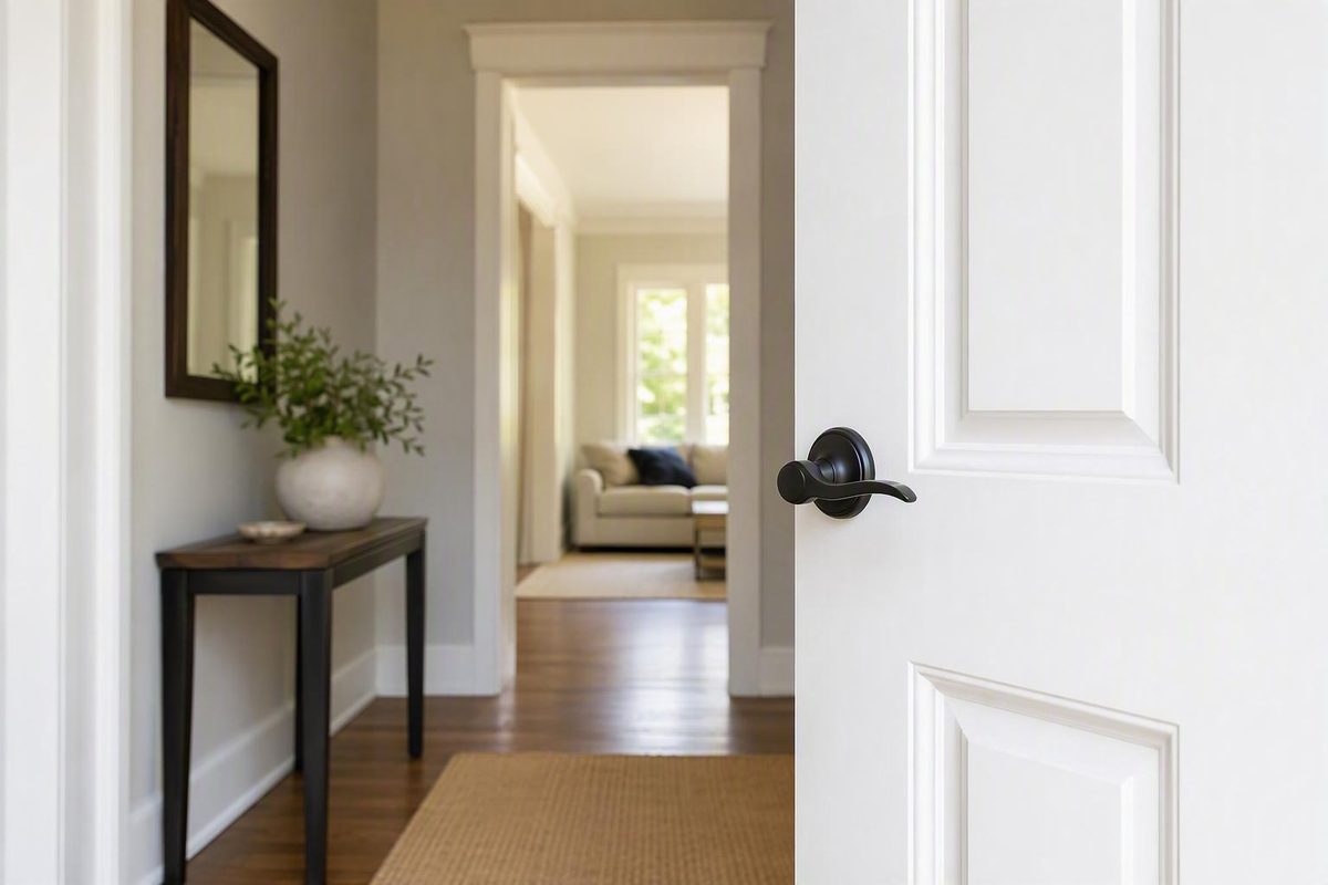
The short answer: start at a 36-inch centerline for a typical home
For an ordinary North American residential door, a practical starting point is to place the center of the knob or lever approximately 36 inches above the finished floor. That is about 915 mm. Treat this as a commercially reported residential convention—not a universal legal standard or a statistically established average across every type of door, building, or country. A different location may be required by the existing door preparation, project drawings, selected hardware, occupants’ needs, or applicable rules. A North American door installer describes 36 inches as the customary finished-floor measurement.
The 36-inch centerline is most useful when installing a conventional knob or lever on a new bedroom, bathroom, closet, or similar interior door in a typical home. Before adopting it, check whether:
- The slab is already bored or otherwise prepared for hardware.
- A replacement door must align with an existing strike.
- Nearby doors establish a consistent centerline.
- The exact hardware template requires a particular preparation.
- The plans or door schedule specify another location.
- The opening is accessible, fire-rated, part of a means of egress, or otherwise regulated.
- The people who will use the door would benefit from a tested residential adjustment.
One door-hardware manufacturer describes 36 to 38 inches as ergonomic for many users, but it does not provide independent research establishing that range as optimal for everyone. Treat it as commercial guidance rather than a proven ergonomic rule. The same manufacturer also instructs installers to measure from the floor to the handle center.
Useful rounded conversions are:
- 34 inches ≈ 864 mm
- 36 inches ≈ 914.4 mm, commonly rounded to 914 or 915 mm
- 42 inches ≈ 1,067 mm
- 48 inches ≈ 1,219 mm
These conversions are consistent with the inch-and-millimetre dimensions used in republished hardware-height provisions; the intermediate values are direct unit conversions. For example, the Illinois provision pairs 34 inches with 864 mm and 48 inches with 1,219 mm.
Do not average the endpoints of the familiar 34–48-inch accessibility range and assume the result is an ideal handle height. A permitted range identifies boundaries under a particular requirement. It does not reveal which point is most common, comfortable, or appropriate for a specific door. The midpoint is 41 inches, but that arithmetic does not make 41 inches the average or preferred door-handle height. The federal accessibility guide identifies the range as a mounting zone for operable hardware, not an ergonomic scale.
Keep three concepts separate throughout the project:
- Customary residential placement: approximately 36 inches above the finished floor is a practical North American starting point.
- Accessibility limits: covered accessible doors place the relevant operable hardware within a specified zone.
- Project-specific legal requirements: the jurisdiction, adopted code edition, building use, door classification, and project documents determine what actually governs.
This distinction prevents two common errors: treating customary practice as law and treating a compliance range as an average.
Average, standard, and permitted range do not mean the same thing
The phrase “average door handle height” is often used casually, but it can refer to several different ideas. Determine which one matters before choosing a dimension.
A customary height is a dimension commonly used by builders, installers, or manufacturers. It may simplify coordination and make adjacent doors look consistent, but it does not necessarily come from a statistical survey or legal requirement. The familiar residential centerline belongs mainly in this category.
A standard location is more ambiguous. It might mean:
- An industry recommendation
- A manufacturer’s standard preparation
- A dimension in project specifications
- A contractor’s usual practice
- A requirement in an adopted code or accessibility standard
Calling a position “standard” does not establish who issued the standard, what hardware it covers, or where it applies.
A permitted range establishes minimum and maximum limits under a particular rule. Every position within that range may satisfy the height provision, subject to how the hardware is measured and any other applicable conditions. The range itself does not identify the most popular or comfortable position.
For doors and gates required to be accessible under the relevant federal standards, the official U.S. Access Board guide places the operable portions of manual-door hardware between 34 inches minimum and 48 inches maximum above the floor. It does not describe 36 inches as the average residential height or recommend the midpoint of the range. The Access Board illustrates and explains the 34–48-inch operable-hardware zone.
Jurisdiction-specific building-code language may resemble that federal range while having its own scope and exceptions. For example, republished Illinois Building Code 2021 language states that handles, pulls, latches, locks, and other devices used for normal door operation must be installed 34–48 inches above the finished floor. It also identifies limited exceptions. That provision must not be generalized into a nationwide rule; local adoption, amendments, and the current governing edition still need to be confirmed.
Nor should federal accessibility requirements be assumed to cover every door in every private residence. Applicability depends on the facility, building use, covered area, door function, and governing rules. A bedroom door in a detached private home and a door on an accessible route in a public facility do not automatically require the same analysis.
| Context | Useful figure | What the figure means | What must be verified |
|---|---|---|---|
| Customary North American residential placement | Residential baseline described above | A practical starting centerline for many ordinary knobs and levers | Existing bores, occupants, plans, instructions, door function, and local rules |
| U.S. accessible hardware | 34–48 in. above the floor | Permitted zone for relevant operable portions on covered accessible doors and gates | Whether the opening must comply, which part is operable, and whether an exception applies |
| Illinois code example | Jurisdiction-specific range stated above | Republished provision for hardware used in normal door operation | Local adoption, amendments, code edition, building use, and door classification |
| Architectural door pull recommendation | 42-in. center | Reported industry-recommended center location for an architectural pull—not an average for all handles The recommendation is discussed by door-hardware specialist Lori Greene | Pull length, usable gripping area, project documents, accessibility interpretation, and AHJ approval |
The table is not a menu from which to select whichever figure looks best. Each row answers a different question. Customary residential placement concerns ordinary home installations; accessibility figures define a compliance zone where applicable; and the pull recommendation concerns a particular hardware category.
Measure from the finished floor to the hardware’s operating point
For a conventional cylindrical knob or lever, measure vertically from the finished floor to the spindle or handle centerline.
The finished floor is the final walking surface after construction is complete. It may be tile, hardwood, laminate, resilient flooring, carpet, or another installed finish. It is not the subfloor, unfinished slab, or an assumed future floor level.
This matters when flooring has not yet been installed. If a future tile or wood assembly raises the walking surface, a mark made from the unfinished substrate will produce a lower final handle position than intended. On renovation work, account for flooring that will be added, removed, or replaced before making permanent marks.
Do not use the bottom edge of the door as the primary vertical reference. Its relationship to the floor can change because of:
- Door undercuts
- Thresholds
- Carpet clearance
- Uneven floors
- Adjustment of the slab within the frame
- Different floor elevations on opposite sides
- Sweeps or other required clearances
Two doors bored at the same distance from their bottom edges can therefore end up with different finished-floor centerlines. Measure from the actual finished-floor reference and account for any transition or threshold.
The visual midpoint of the trim is not always the operating point. With a conventional knob or lever, the spindle and trim are often arranged around the same centerline. With other products, the relevant part may be a touchpad, crossbar, thumbturn, latch-releasing component, or usable grip area.
That distinction is especially important for nonstandard hardware:
- A long vertical pull may be grasped at several heights.
- A panic device may use a broad touchpad or crossbar.
- An extended thumbturn may have a particular latch-operating portion.
- Access-control components may not share the lock’s visual centerline.
Do not copy the residential knob-center method without first identifying what the user must actually operate.
A planning diagram can clarify the measurements. The following is not to scale and does not imply that every residential door is subject to accessibility requirements:
                         DOOR FACE

              ┌──────────────────────────┐
48 in.        ├ ─ upper limit of an      │
              │   applicable accessible  │
              │   hardware zone          │
              │                          │
36 in.        ├──── residential start ───●  spindle center
              │                          │
34 in.        ├ ─ lower limit of an      │
              │   applicable accessible  │
              │   hardware zone          │
              └──────────────────────────┘
════════════════ FINISHED FLOOR ════════════════

Door edge  │<────── backset ──────>│ bore center
Use this sequence before drilling:
- Confirm the final floor elevation. If the finish is not installed, use a reliable finished-floor datum from the project documents.
- Measure vertically. Mark the intended hardware centerline.
- Draw a short level line. A line is easier to verify than a single dot.
- Measure the backset. Mark the intersection between the backset and horizontal centerline.
- Transfer the preparation carefully. Identify the corresponding locations on both faces and the door edge.
- Overlay the exact manufacturer’s template. Let that template control bore sizes and component relationships.
- Check alignment and clearance. Confirm that the latch will meet the strike and that the complete trim footprint clears stops, panels, glass, and molding.
- Verify the setup again. Check the floor reference, height, backset, swing, handing, and template orientation before cutting.
If the door is already hung, close it and compare the proposed latch centerline with the frame preparation.
Accessibility involves more than mounting height
Official accessibility guidance generally requires the operable portions of manual-door hardware on covered accessible doors and gates to be located 34–48 inches above the floor. It does not automatically impose that range on every door in every privately occupied home. A door-hardware manufacturer’s accessibility summary reproduces the range and related one-hand operability requirements.
The phrase operable portion matters. It focuses attention on the part a person must use to unlatch, open, or otherwise operate the door. Depending on the product, that could be a lever, knob, thumbturn, pull, panic bar, push plate, or access-control component.
Accessible hardware must also avoid operation that requires tight grasping, pinching, or twisting of the wrist. That is one reason a lever may be easier for some people to operate than a conventional round knob. Force, reach, clearance, and the complete operating motion can still create barriers.
Mounting height is only one part of an accessible opening. The official guidance also generally identifies:
- A minimum 32-inch clear opening, subject to specified measurement details and exceptions
- Required maneuvering clearances
- Limits and details for thresholds
- An illustrated 5-pound-force opening-force limit that excludes exterior hinged doors and fire doors
- At least five seconds for a door closer to move from 90 degrees to 12 degrees
These figures and their qualifications appear together in the official Access Board doorway guidance cited earlier. They should be evaluated as a coordinated set rather than isolated specifications.
A handle located within the permitted height zone does not make a doorway accessible by itself. The opening may remain unusable if:
- The clear opening is insufficient.
- A wall, cabinet, or furniture blocks the approach.
- The threshold creates a barrier.
- Excessive force is needed to open the door.
- The closer shuts too quickly.
- The hardware demands tight grasping or wrist twisting.
- The latch side lacks usable maneuvering space.
- The nominally reachable component cannot be operated effectively.
Door classification can also change the analysis. Exterior hinged doors, fire doors, automatic doors, gates, existing openings, and doors serving particular rooms may be subject to different provisions or exceptions.
For an ordinary alteration inside a private home, trying a mock-up with the residents can be a useful design step. For a public, commercial, workplace, multifamily common-area, or accessible-route door, informal testing is not a substitute for compliance review. Check the current adopted requirements, consult the project design professional where applicable, and resolve uncertain interpretations with the local Authority Having Jurisdiction, or AHJ.
Adjusting placement for door type, hardware, and occupants
Moving away from the customary residential centerline may be reasonable or necessary, but the reason should be more specific than “the door looks tall” or “the permitted range allows it.” Consider the door, hardware, users, preparation, and applicable requirements together.
Existing preparation and replacement doors
A pre-bored slab immediately limits the available choices. Reusing the preparation is often easier than repairing and reboring the door, but first confirm that the replacement hardware matches:
- The existing backset
- Main-bore and edge-bore diameters
- Door thickness
- Latch-face preparation
- Center-to-center spacing for interconnected or multipoint hardware
- Existing strike location
- The complete trim footprint
When replacing one door in a hallway or room, measure the adjacent handle centerlines. Matching them may improve visual consistency and preserve alignment with an existing frame preparation.
Consistency does not justify repeating a condition that conflicts with governing requirements. If the replacement affects an accessible, egress, fire-rated, or otherwise regulated opening, approved documents and applicable rules take priority over neighboring handle heights.
Tall doors
An 8-foot door does not inherently require a proportionally higher handle. Commercial residential guidance reports that the familiar 36-inch centerline can remain in use on an 8-foot door rather than moving upward solely because the slab is taller. MOD Lighting’s installation article specifically reports retaining that location on an 8-foot door.
A different position may still be specified for specialized hardware or a particular design. Door height by itself is not enough reason to change the operating height.
Knobs and levers
Compatible cylindrical knobs and levers are commonly positioned by reference to the spindle or lock-bore centerline. Do not assume, however, that any knob and lever are interchangeable merely because their centerlines appear similar.
Confirm the selected product’s:
- Lock preparation
- Backset
- Door-thickness range
- Latch type
- Through-bolt positions
- Handing
- Required clearances
The operating experience also differs. Product selection should still account for latch force, projection, return clearance, room function, privacy, and the intended users.
Long pulls and panic hardware
A long vertical pull should be evaluated according to the portion a user can actually grasp, not automatically by treating its decorative midpoint as a knob spindle. Panic hardware likewise must be considered in relation to its latch-releasing touchpad or crossbar.
The architectural-pull center recommendation shown in the comparison table is not an average for every handle and is not a universal legal requirement. The supplied industry discussion also states that codes and standards do not conclusively settle whether every part of a long pull must fit inside an accessible zone or whether an adequately usable portion is sufficient.
That uncertainty should not be converted into a do-it-yourself compliance rule. For an unusually long pull on a covered accessible opening, obtain project-design review and ask the AHJ to resolve the interpretation when the governing text is unclear.
Occupants and individual use
A private residential installation can account for the people who will use the door every day. Avoid unsupported rules assigning particular heights to children, wheelchair users, or people of a certain stature. Instead, mock up the proposed position.
Place removable tape at the candidate location and, if possible, let the occupants operate a sample handle. Observe:
- Reach from both sides
- Wrist position
- Balance
- Hand clearance
- Approach space
- Conflicts with furniture or walls
- Ease of unlatching and pulling or pushing
A handle that feels convenient from an open hallway may be harder to use from inside a small bathroom or a room with limited maneuvering space.
Where accessibility or another project requirement applies, test user preferences within those constraints. Personal preference can help choose among permitted options, but it does not override governing requirements.
Door handle heights vary by country and jurisdiction
The supplied evidence does not establish a reliable global average. Approximately 36 inches, or 915 mm, is best understood as a commonly reported North American residential starting point rather than an international norm.
Customary practice can differ elsewhere. A UK door-hardware retailer reports 1,050 mm as a typical position for many internal door handles and cites 900 mm as the preferred accessible lever height under BS 8300-2:2018. The retailer also distinguishes common practice from accessibility guidance. Because the underlying British Standard and applicable regional regulations are not supplied here, neither figure should be presented as a universally binding UK legal requirement. Door Controls Direct explains the distinction between the reported 1,050-mm convention and the cited 900-mm preference.
Requirements can also differ within the same country. States, provinces, municipalities, building uses, and adopted code editions may impose different conditions. Local amendments can narrow or otherwise modify a broadly familiar range.
Illinois is one bounded example: its republished 2021 code language uses the range discussed earlier for hardware involved in normal door operation. That is evidence of a particular jurisdictional provision, not a nationwide residential rule.
A 2017 industry article reports a narrower 34–44-inch range in California. Because that statement is dated secondary reporting rather than the current adopted code for an identified project, it should be treated as a prompt to verify local requirements—not as installation authority. The dated report appears in the same industry discussion of accessible mounting heights.
Use this verification hierarchy:
- Project plans and specifications. Check door schedules, hardware groups, elevations, accessible-opening designations, and approved products.
- Current manufacturer instructions. Use the template supplied for the exact model, not one for similar-looking hardware.
- Adopted building, accessibility, fire, and related provisions. Confirm the applicable edition and local amendments.
- The local AHJ. Request clarification when an existing condition, long pull, access-control component, exception, or unusual preparation does not fit the ordinary case.
Customary practice should fill a design choice only after higher-priority requirements have been addressed.
The pre-drilling checklist: height is only one measurement
A handle can be at the intended height and still fail to fit, latch, clear the trim, or align with the strike. Treat the complete door preparation as a coordinated layout.
Stop before drilling a regulated opening: Do not modify a fire-rated, egress, accessible, commercial, access-controlled, or otherwise regulated door solely from a general DIY guide. Obtain the approved door and hardware documentation and involve the responsible professional, supplier, or AHJ as appropriate. Drilling or altering a listed assembly without confirming its documentation can create project and approval problems.
Establish the controlling conditions
Before making a permanent mark:
- Identify the country, state or province, and municipality.
- Determine the building use and door function.
- Check whether the opening is regulated.
- Confirm the final finished-floor level.
- Select the intended handle or lock centerline.
- Compare it with project drawings and adjacent doors.
- Inspect the slab and frame for existing preparation.
- Obtain the template for the exact hardware model.
If the project includes a door schedule or hardware schedule, use it. A generic online diagram should not override contract documents or the selected product’s instructions.
Verify the backset
The backset is the horizontal distance from the door edge to the center of the handle or lock bore.
Commonly reported residential backsets are 2-3/8 inches and 2-3/4 inches, but neither should be assumed. The same manufacturer guide lists 1-3/8 inches as a usual interior-door thickness while warning installers to confirm backset, thickness, latch type, and locking compatibility for the selected product. The dimensions and compatibility checks appear in YALIS’s measurement guide.
Use the latch supplied with the lockset and set the exact template to the required backset. For replacement work, measure the existing preparation rather than identifying it by appearance.
Check door thickness
Measure the actual door thickness at a clean, representative location. The commonly reported interior dimension noted above is not universal. Exterior doors, custom slabs, older doors, glass doors, and specialized assemblies may differ.
Confirm that the spindle, fasteners, through-bolts, latch, and trim support the measured thickness. Do not assume an extension kit exists unless the manufacturer lists one for the exact model.
Confirm all hardware relationships
Verify:
- Latch type: drive-in, square-corner faceplate, rounded-corner faceplate, tubular latch, mortise lock, or another preparation
- Handing: reversible or specifically handed hardware
- Lock function: passage, privacy, keyed entry, storeroom, classroom, dummy, interconnected, or another function
- Strike alignment: vertical position, projection, lip length, and frame preparation
- Main-bore diameter: compatibility with the lock body and trim
- Edge-bore position and diameter: correct intersection with the main bore
- Trim clearance: space around glass, molding, panels, stops, and frames
- Existing holes: compatibility with the new trim footprint or an approved repair
- Door swing: push side, pull side, secure side, and room side
- Adjacent conditions: walls, cabinets, railings, shutters, and door stops
- Required documentation: suitability of the selected hardware for any regulated opening
Treat deadbolt spacing as product-specific
Commercial sources conflict on deadbolt spacing. One recommends positioning a deadbolt 4–6 inches above the main handle, while another recommends 6–12 inches. The disagreement demonstrates why neither range should be treated as universal. The 4–6-inch recommendation appears in Magic Window’s guide, while the 6–12-inch recommendation appears in MOD Lighting’s article.
Determine the actual spacing from:
- The lock or handleset manufacturer’s template
- Existing slab and frame preparation
- Required clearance between escutcheons
- Project elevations and hardware schedules
- Door construction and reinforcement
- Applicable accessibility, egress, fire, and security requirements
This is particularly important for handlesets, interconnected locks, multipoint systems, narrow-stile doors, and doors containing panels or glass. Do not position a deadbolt merely because an area of the door face appears open.
Mark and verify before cutting
After confirming the dimensions:
- Mark the centerline lightly on both faces and the edge.
- Confirm that the three marks align.
- Check the backset from the correct door edge.
- Tape the exact drilling template in place.
- Verify that the template is oriented correctly for the door.
- Check the full trim footprint, not just the bore.
- Compare the latch line with the intended strike location.
- Dry-fit components or use a physical template where possible.
- Recheck the finished-floor reference.
- Begin irreversible work only after the complete layout agrees.
Stop and obtain product-specific guidance when the work involves glass, a narrow stile, concealed components, specialized reinforcement, or an existing preparation that does not match the template.
The practical decision rule is simple: use the customary residential starting point only when the door, selected hardware, occupants, existing preparation, plans, and governing requirements do not indicate otherwise.
Frequently asked questions
Is 36 inches the standard height for every door handle?
No. It is a commonly reported starting point for many North American residential knobs and levers, not a universal legal standard or proven global average.
A pre-bored slab, existing strike, project specification, accessible opening, long pull, panic device, or specialized lock may require a different location. Confirm the actual door and hardware conditions before drilling.
Does the ADA require door handles to be 34–48 inches above the floor?
For covered accessible doors and gates, the relevant requirement generally applies to the operable portions of manual-door hardware within that zone. It does not automatically cover every door in every private home. A third-party hardware guide summarizes the range and notes that accessible hardware must avoid tight grasping, pinching, and wrist twisting.
Height alone does not establish accessibility. Clear opening, maneuvering space, thresholds, operating force, closing behavior, and the usability of the selected hardware may also matter.
Should an 8-foot door have a higher handle?
Not solely because it is taller. Commercial guidance reports that an 8-foot residential door can retain the familiar residential handle position. Raising the hardware in direct proportion to the slab height is not inherently necessary.
Use a different position only when the drawings, existing preparation, selected hardware, occupants, or governing requirements provide a reason.
Where should I measure a knob, lever, or long pull?
For a conventional knob or compatible lever, measure vertically from the finished floor to the spindle or lock-bore centerline. Measure the backset horizontally from the door edge to that same centerline.
For a long pull, panic device, touchpad, crossbar, or other nonstandard product, identify the component actually used to operate the door. Do not assume the decorative midpoint is the controlling measurement. Refer ambiguous accessible installations to the designer and AHJ.
How far above a door handle should a deadbolt be installed?
The supplied commercial guidance does not establish a reliable universal spacing. Use the exact lock or handleset template, existing door preparation, required trim clearance, project documents, and applicable requirements.
Before drilling either bore, verify that the deadbolt, latch, strikes, reinforcement, fasteners, and decorative trim will align.
Final decision before drilling
For an ordinary North American residential knob or lever, approximately 36 inches above the finished floor remains a useful starting centerline. It is the beginning of the layout process, not the final authority.
Before cutting the door, verify the finished-floor reference, exact manufacturer’s template, backset, door thickness, latch preparation, trim clearance, strike alignment, occupants’ needs, and project requirements. Accessible, public, commercial, fire-rated, egress, and other regulated openings require project-specific review rather than reliance on a customary residential dimension.